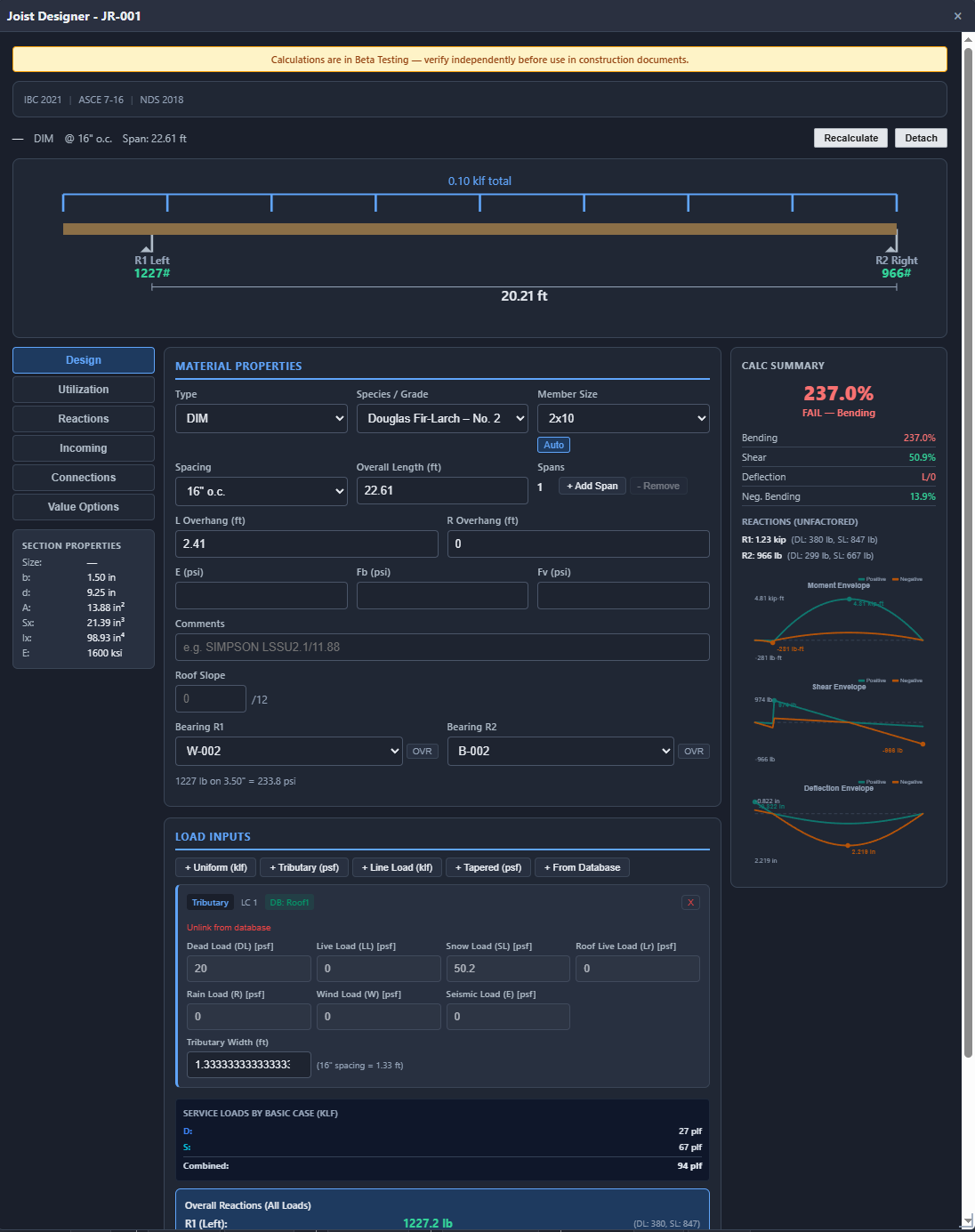
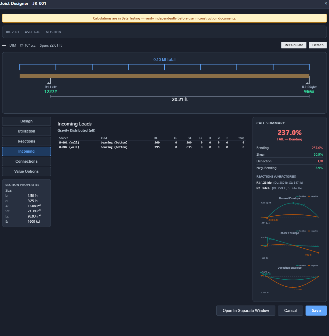
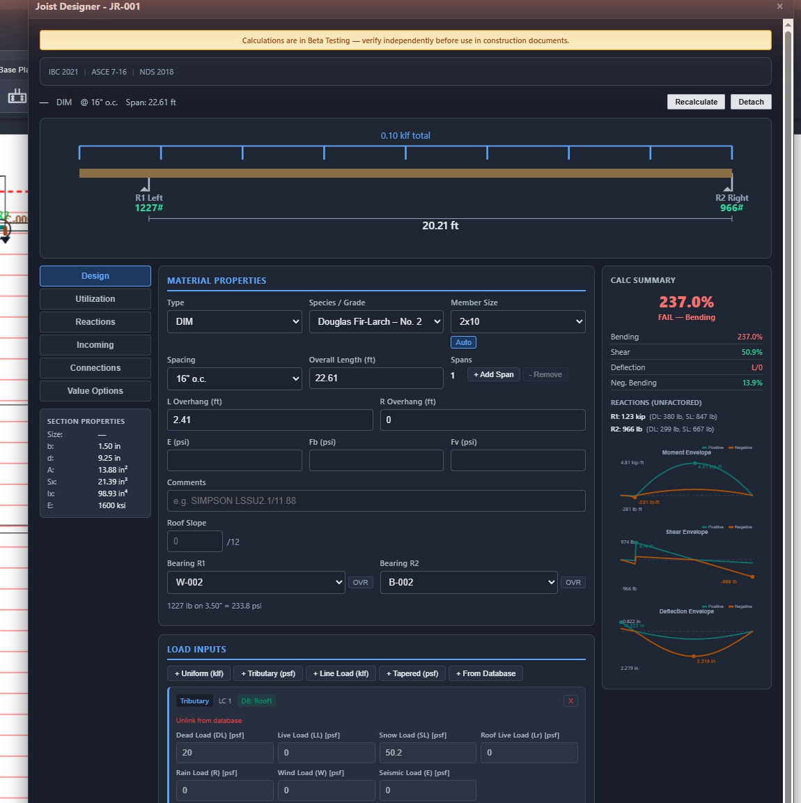
JR-001 — section data
Section properties print live in the sidebar: b 1.50 in, d 9.25 in, A 13.88 in², Sx 21.39 in³, Ix 98.93 in⁴, E 1,600 ksi.
Reactions stay unfactored and split by case — R1 = 1.23 kip (DL 380 lb, SL 847 lb), R2 = 966 lb (DL 299 lb, SL 667 lb).
The seat itself is checked: 1,227 lb on 3.50 in of bearing = 233.8 psi against the species' perpendicular-to-grain allowable.
Joist
DIM 2×10 DF-L No. 2 · 16″ O.C. · OVERALL 22.61 FT · OVERHANG 2.41 FT
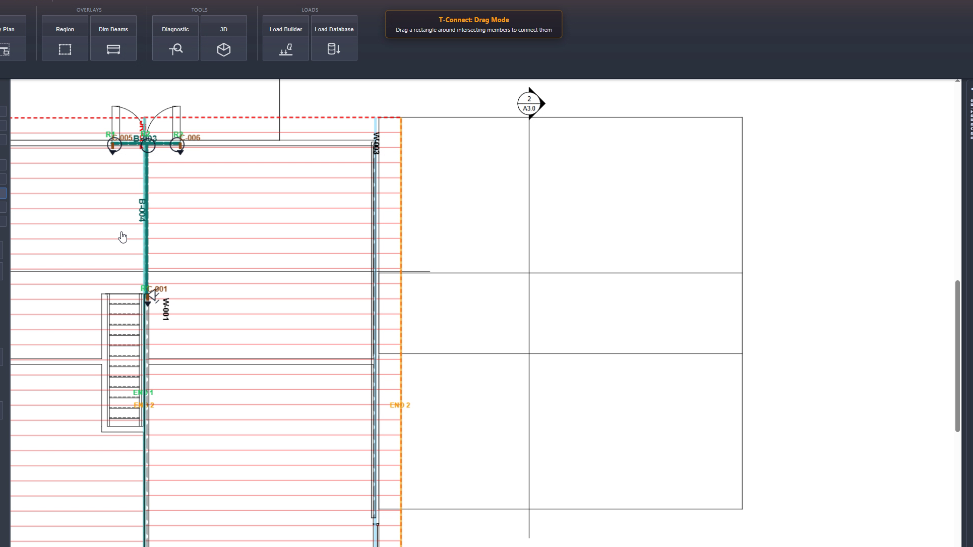
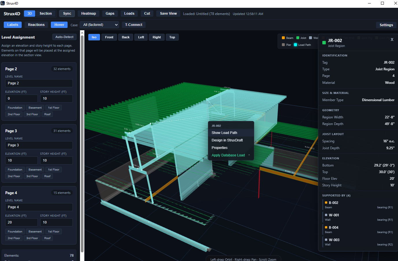
A joist member is a field, not a single line — set size, species and grade, spacing at 12/16/19.2/24″ o.c., and overhangs each end, and the loading diagram redraws above the inputs. Tributary dead and snow loads come from the load database and stay linked to it — JR-001 carries 20 psf dead and 50.2 psf snow from the entries that define them. Bearings R1 and R2 name the members underneath — wall W-002 and beam B-002 here — each with the reaction it receives, split into dead and snow. The summary caught this one live: 237.0% FAIL, governed by bending, with moment, shear, and deflection envelopes plotted at the right.