P-1.0Products
The suite, sheet by sheet.
StruxDraft drafts and checks the structure on your plans. StruxCalc runs single members on the same engine. Strux4D proves the load path in 3D — and its free web viewer runs in your browser, no install.
P-2.0SD-01 · The flagship
StruxDraft
Import the architect's plans, draw the structure over them, and every member is checked the moment you place or change it. The plans, the members, the loads, and the checks live in one .struxdraft file.
WINDOWS · v0.3.7 · .STRUXDRAFT
IMPORT
Drop in the PDF plan set and scale it once off a known dimension.
DRAW
Place joists, beams, walls — most connections happen automatically as you draw.
CONNECT
T-Connect drags a rectangle over intersections; loads quick-apply from the database.
VALIDATE
Load arrows and the utilization heatmap in 3D — hover any member for its numbers.
EXPORT
Calc report, key plans, and drafting markups — PDF or DXF.
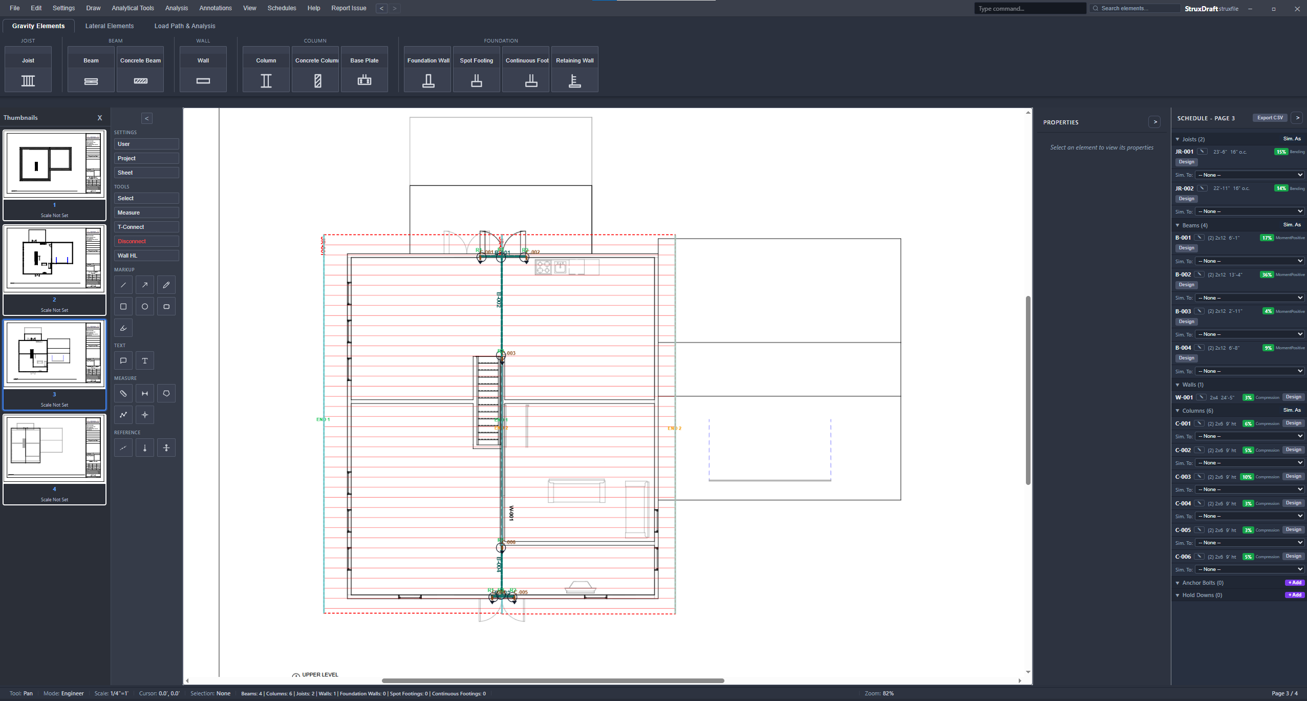
The plan is the model.
There is no separate analysis file to keep in sync. Members are drawn at true scale on the sheet, loads transfer where members touch, and the schedule fills itself row by row. Change a section and every downstream check re-runs — reactions, the members that carry them, and the schedule chip colors.
- Connected load flow — joists load beams by tributary width, walls transfer plf, beams drop R1/R2 reactions onto columns with DL/LL/SL kept separate, and columns accumulate axial down to footings. Circular references are detected and flagged.
- Live schedules — every member lands in its schedule row with size, spacing, span, and a utilization chip; the same table drops onto a sheet as a drafting table or exports to CSV.
- Drafting on the same sheets — measure, annotate, cloud, and call out sections next to the members they reference; markups print with the package.
- NDS 2015/2018/2024 · AISC 360-10/16/22 · ACI 318-14/19/25 · TMS 402-13/16/22 · SDPWS 2015/2021 · ASCE 7-22 · IBC — editions selectable per project
P-2.1Member designers
13 member types. Each with its own designer.
Every type opens a full designer dialog — geometry, material, loads, and the live calc summary with its governing check. These are unedited captures from the test-strux project.
HOVER ANY CELL FOR DETAIL
 Beam — B-001
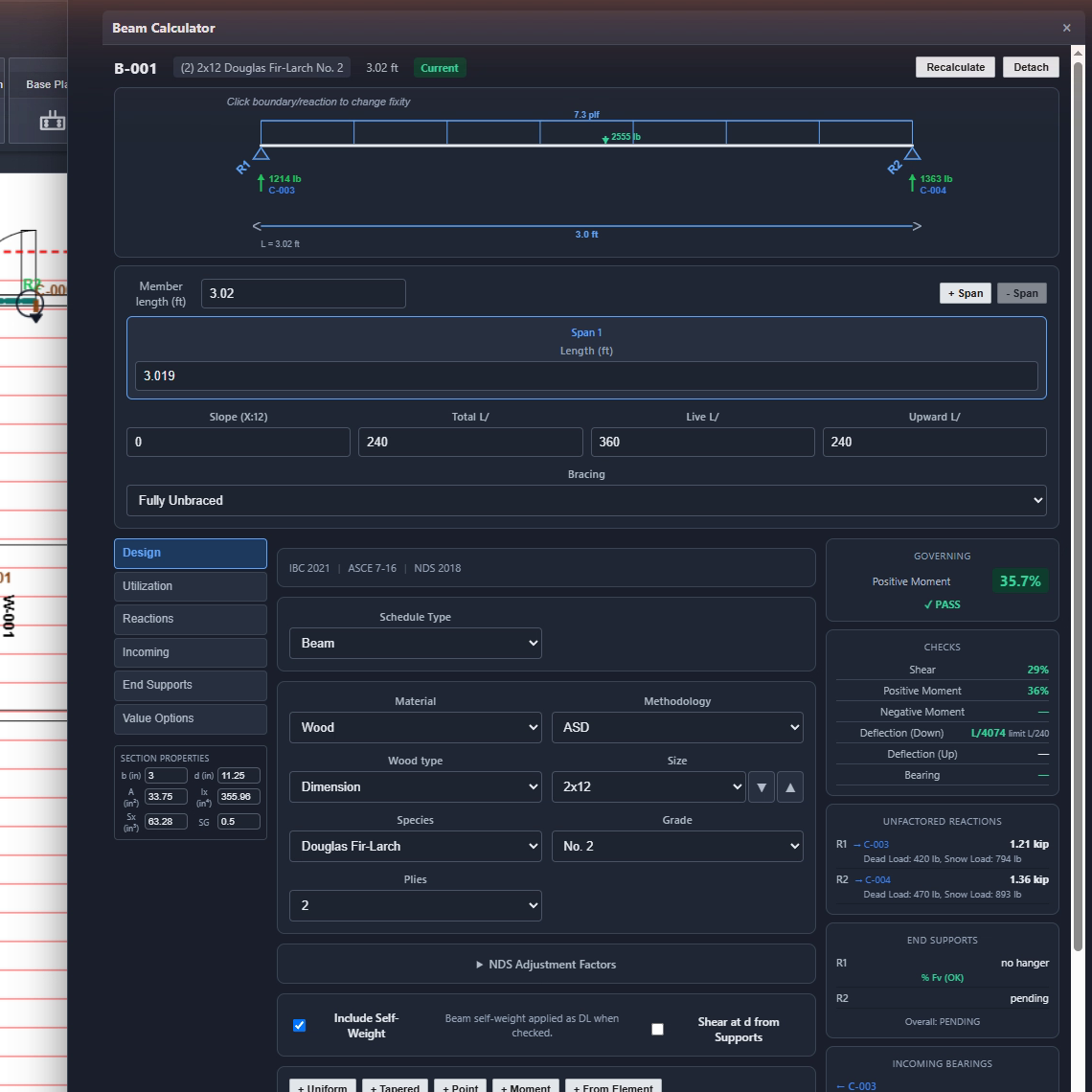
Beam designer
B-001 is a (2) 2×12 DF-L No. 2 on a 3.02 ft span, governing on positive moment at 35.7%. The span diagram draws its distributed and point loads with editable supports; the checks panel lists shear, moment, deflection (L/4074 against L/240), and bearing, and R1/R2 land on columns C-003 and C-004 with dead and snow kept separate. Multi-span, overhangs, and partial loads use the same dialog.
 Joist — JR-001
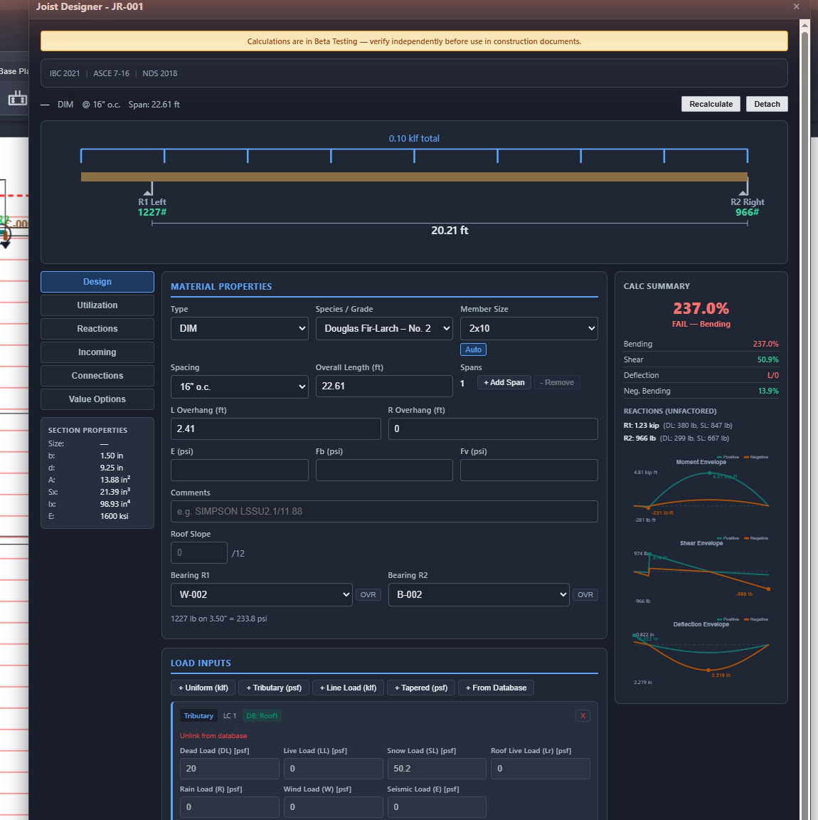
Joist designer
JR-001 is a 2×10 DF-L No. 2 at 16″ o.c. asked to span 22.61 ft — the summary reads 237.0% FAIL, governed by bending, with moment, shear, and deflection envelopes drawn at right. Joist regions take rectangular or polygon boundaries, DIM/LVL/TJI sections, and variable spacing; the region loads its supporting beams by tributary width. The same failing number appears on this joist in the 3D heatmap below.
 Column — C-001
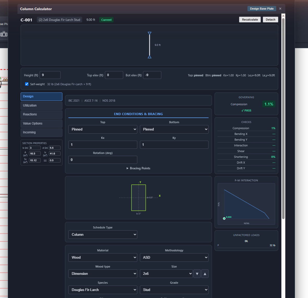
Column designer
C-001 is a (2) 2×6 DF-L Stud at 9 ft, pinned top and bottom with Kx = Ky = 1.00, governing on compression at 1.1%. The dialog runs the full Cp stability analysis, checks bending about both axes plus interaction, and plots the P-M interaction diagram with the design point on it. Columns auto-place at beam endpoints and pick up reactions as unfactored DL/LL/SL.
 Wall — W-001
Wall designer
W-001 is 2×4 studs at 16″ o.c., 8 ft tall over a 24.8 ft run, passing at 33.4% with compression governing under D+S. The summary breaks load down per stud — 347 lb dead, 667 lb snow — and totals the wall line at 0.75 klf combined. Loads arrive as tributary psf, plf, or directly from the joists and beams bearing on the wall.
 Foundation wall — FW-001
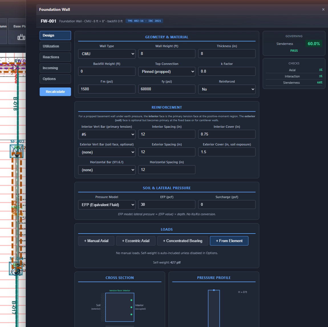
Foundation wall designer
FW-001 is an 8 ft × 8″ CMU wall checked to TMS 402-16 under IBC 2021 — slenderness governs at 60.0% with axial and interaction checks beside it. Inputs cover f′m, bar size and spacing for interior and exterior faces, backfill height, and an equivalent-fluid soil pressure model; the dialog draws the cross-section and lateral pressure profile as you edit.
 Spot footing — SF-001
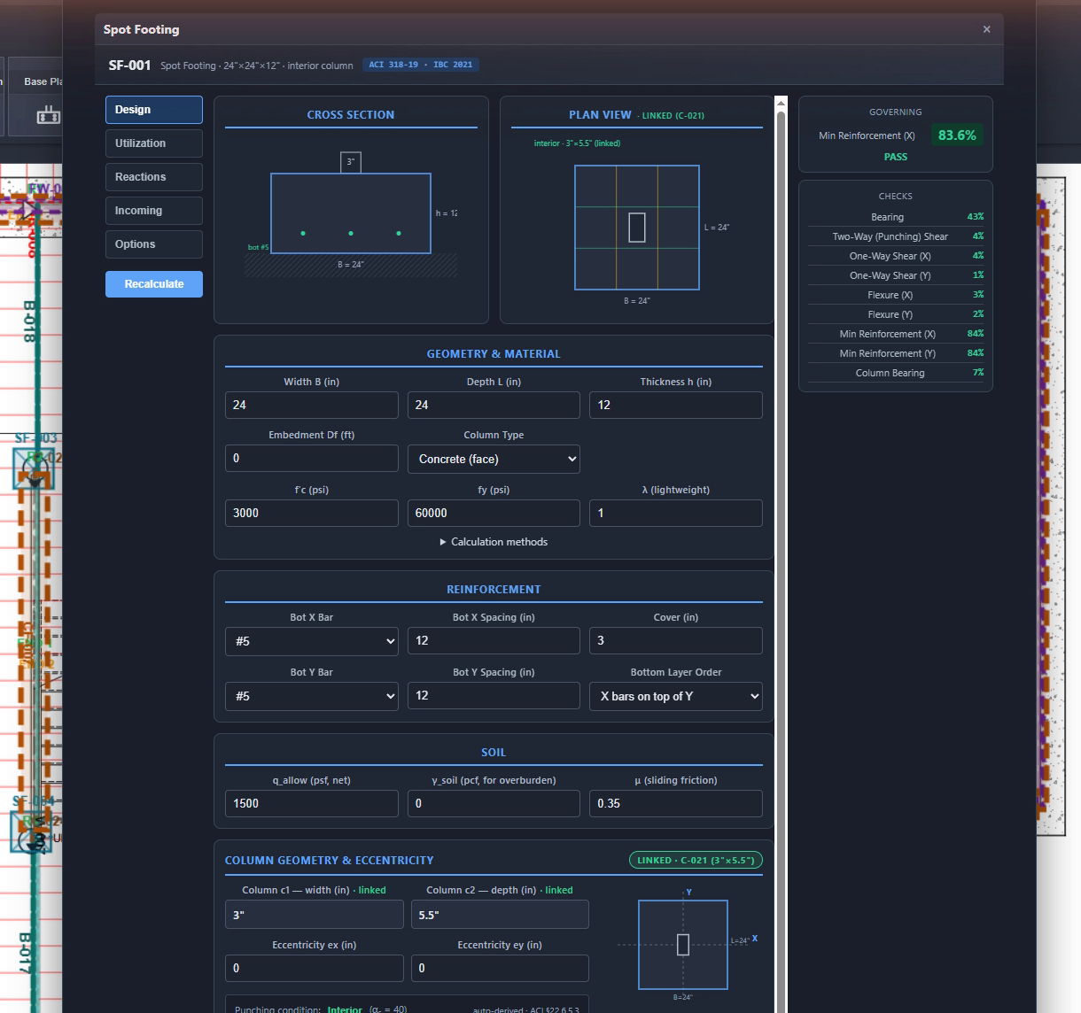
Spot footing designer
SF-001 runs the full ACI 318 set: two-way punching shear at d/2 from the column face, one-way shear at d, flexure each way, development length, and minimum reinforcement — the governing check sits at the top with its utilization. Geometry, bar layout, allowable bearing, and the supported column's geometry are all inputs; the accumulated axial load arrives from the column above automatically.
 Continuous footing — CF-001
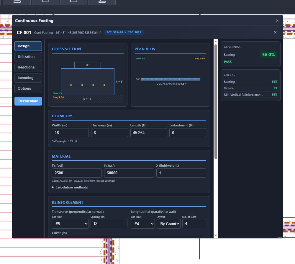
Continuous footing designer
CF-001 is a 16″ × 8″ strip running 45.26 ft under a bearing wall, checked to ACI 318-19 with bearing governing at 56.0% and flexure at 1%. Transverse and longitudinal reinforcement are laid out by spacing or by count, self-weight (133 plf here) is included automatically, and the wall line load comes straight from the elements it supports.
All 13 member types — wood · steel · concrete · masonry
Sections & materials
Wood runs DIM, GLB, LVL, PSL, and TJI sections with species and grade from the NDS supplement; steel beams and columns take W-shapes and rectangular or round HSS with full section property tables; concrete and masonry members take f′c, f′m, and reinforcement layout. Section, connector, and load-combination databases are CSV-backed with a user-override layer, so your office's materials live alongside the published tables.
Most connections happen as you draw. T-Connect catches the rest.
Bear a beam on a wall or end a joist region at a beam and the load transfer registers immediately. For framing that crosses without touching endpoints — flush beams under a joist field, a ledger along a wall — switch T-Connect to Drag Mode and pull a rectangle over the intersections: each crossing becomes a connection.
- Quick-apply loads — named load cases live in the project database; apply a stored dead, live, or snow load to any member instead of retyping psf values, and change it once to re-run everything that references it.
- Reactions stay disaggregated — DL, LL, and SL ride separately through every transfer, so combinations factor correctly at the bottom of the stack.

The package prints itself.
One dialog assembles the submittal: cover sheet, design criteria with the project's code editions, table of contents, load path narrative, calculation audit, and a PE certification page — then member-by-member calc sheets, each with its equations and code references. Include or exclude members by tag, type, size, or page.
- Plans go with it — multi-page PDF of the marked-up sheets at 2× resolution, and DXF with per-element layers for the CAD round trip.
- From this exact project — the test-strux model (78 elements, 8 sheets) prints to a 195-page report.
P-3.0SC-02 · Standalone
StruxCalc
The same checking engine without the plan set. Open it for a proposal-stage size, a field question, or an independent check of a drafted design — one member at a time, every step of the work shown.
SAME ENGINE · PRINT TO PDF

Open, size, print.
Every calculation shows its work the way a hand calc does: design values, adjustment factors, equations, intermediate results, and the code citation for each check. Nothing is summarized away.
- Wood — NDS ASD with the full adjustment chain: CD, CM, Ct, CL, CF, Ci, Cr, Cp.
- Steel — AISC 360 flexure with Cb, shear, and axial compression with Euler buckling, LRFD or ASD.
- Concrete & masonry — ACI 318 footing and wall checks; TMS 402 foundation walls.
- Calc sets — save and reload groups of members; print any of them as submittal-ready sheets.
P-4.0AF-03 · Beta
AutoFrame BETA
Give it the wall layout and it frames the level — then every member it places runs through the same checks as one you drew by hand.
INSIDE STRUXDRAFT · NO EXTRA LICENSE
AutoFrame builds a graph from your walls with adaptive endpoint clustering, extracts each room as a planar face — rectangular or not — and runs joists perpendicular to the short dimension. Where a span exceeds its limit it subdivides with a beam; where a wall has an opening it places a header.
Sizing is iterative: each generated member steps through candidate sections until the NDS checks pass, using the same engine as the designers above. Any room can be overridden — its live load, its room type, or the whole framing layout by hand. It's in beta: review what it draws the way you'd review a junior engineer's framing plan.
P-5.0S4-04 · Validation
Strux4D
The hardest part of multi-story design isn't the math — it's making sure every load has a path to the ground. Strux4D assembles your plan sheets into a 3D model and walks that path with you. It ships on the desktop with the suite, and the free web viewer runs in any browser.
DESKTOP + FREE WEB VIEWER
Try it right now — it opens the real test-strux model in your browser.
No install, no account. The viewer loads the same 78-element project shown across this page: assign each plan page an elevation and the floors stack into a model you can orbit, section, and question. Open a .struxdraft file of your own with "Load another file."
FREE · READ-ONLY · OPENS .STRUXDRAFT FILES
 Member selected — W-004
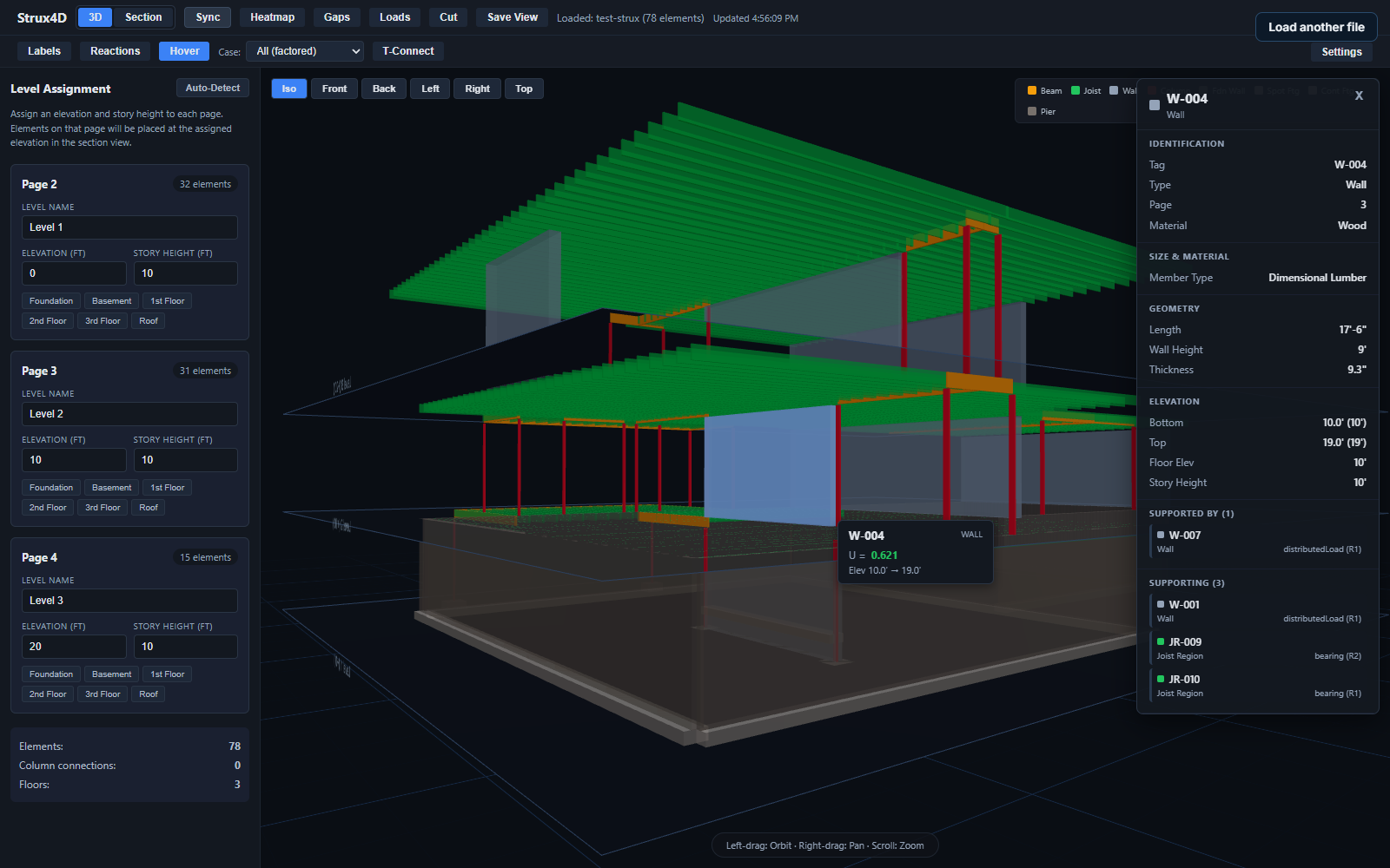
Click any element
Select W-004 and the panel shows its size, material, page, and elevations — then the two lists that matter: Supported by (what holds it up, with bearing side) and Supporting (the joists and beams it carries). Column stacking across floors is detected automatically, so a post that misses the post below reads immediately.
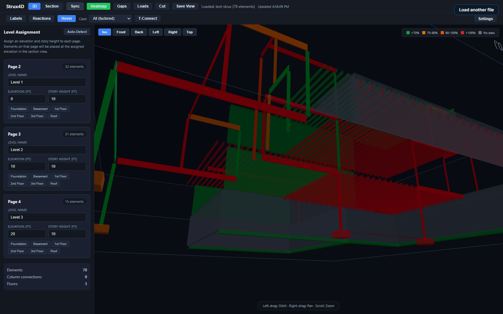 Utilization heatmap
Utilization heatmap
Every member shades from green to red by its governing utilization, so the overstressed framing reads from across the room. Hover any member for its tag, U value, and max deflection — JR-001, the joist failing at 237.0% in its designer dialog above, reads U = 2.370 here. Same engine, same number, two views.
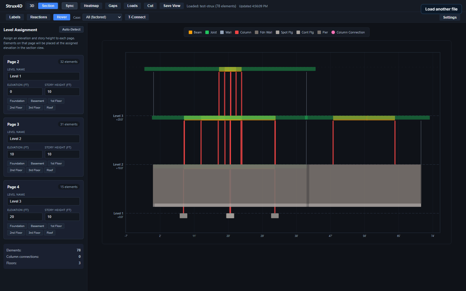 Section view
Section view
Cut the model to a 2D elevation — the test-strux project sections at 0′, 10′, and 20′ with each element type color-keyed and a true-scale ruler below. Use it to check plate heights, joist bearing elevations, and whether a column line actually continues to the foundation.
Same joist. Same numbers. Dialog and model never disagree.
A plugin to carry the framing you design in StruxDraft into your Revit model — members, levels, and tags coming across instead of being redrawn. In development now; beta participants will see it first.
P-7.0Schedule of products
Which tool does what.
ONE ENGINE · ONE FILE FORMAT
| Capability | StruxDraft | StruxCalc | Strux4D |
|---|---|---|---|
| Draft on imported PDF plans, to scale | Included | Not included | Not included |
| Member design checks — NDS · AISC · ACI · TMS | Included | Included | Not included |
| Automatic load transfer between members | Included | Not included | Not included |
| Live schedules on the sheet | Included | Not included | Not included |
| Calc report package with equations & code references | Included | Included | Not included |
| Drafting markups · PDF & DXF export | Included | Not included | Not included |
| AutoFrame automatic framing (BETA) | Included | Not included | Not included |
| 3D model · load arrows · utilization heatmap | Not included | Not included | Included |
| Load-path trace · gap & column-stacking detection | Not included | Not included | Included |
| Section view at true elevations | Not included | Not included | Included |
| .struxdraft project file | Creates & edits | Not included | Reads (read-only) |
| Platform | Windows desktop | Windows desktop | Windows desktop + free web viewer |
| All three run the same calculation engine. Code editions — NDS 2015/2018/2024 · AISC 360-10/16/22 · ACI 318-14/19/25 · TMS 402-13/16/22 · SDPWS 2015/2021 · ASCE 7-22 · IBC — are selectable per project. | |||
P-8.0Issue for review
Put a real project through it.
Bring your plans to the beta. Every check shows its equation.
INVITE-ONLY BETA · WINDOWS · FOUNDERS PRICING FOR EARLY ADOPTERS