01DIM · GLB · LVL · PSL
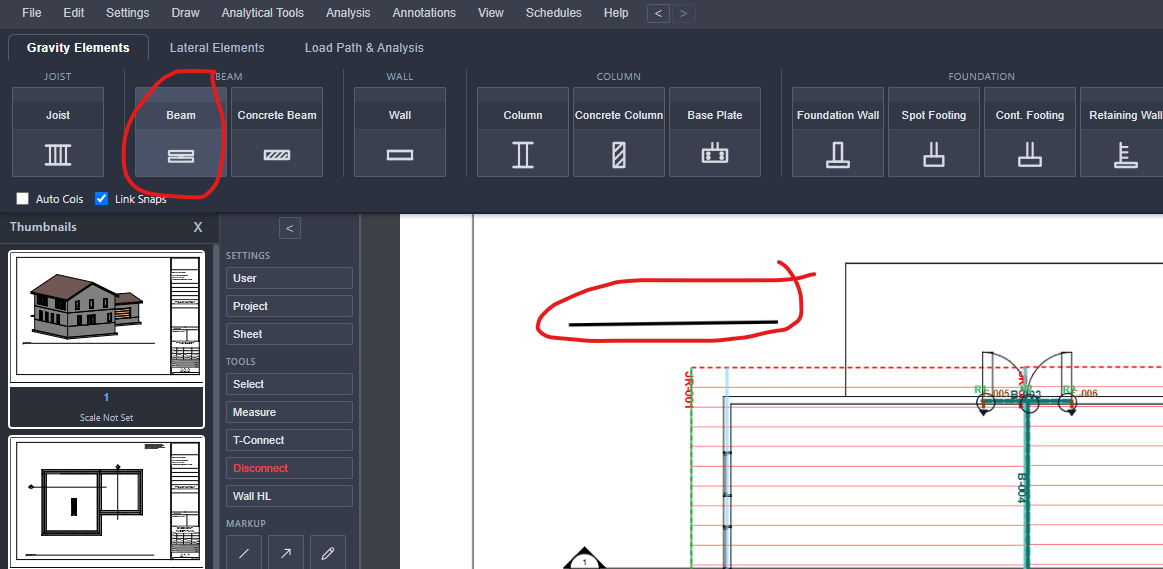
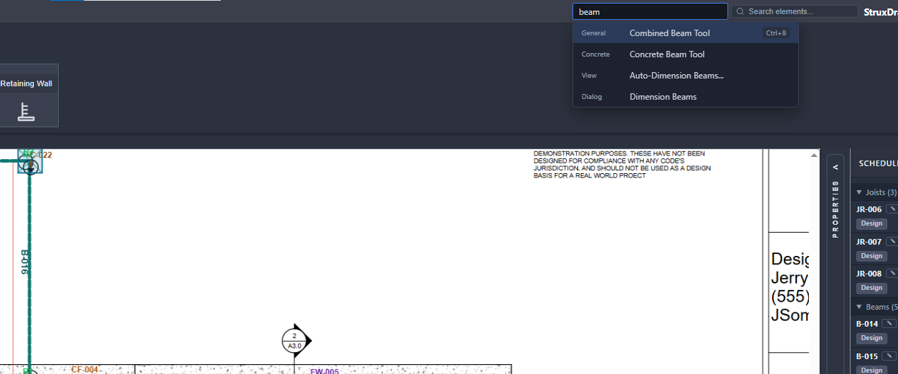
Beam
Multi-span with overhangs each end, roof slope, partial-span and point loads.
02DIM · LVL · I-JOIST
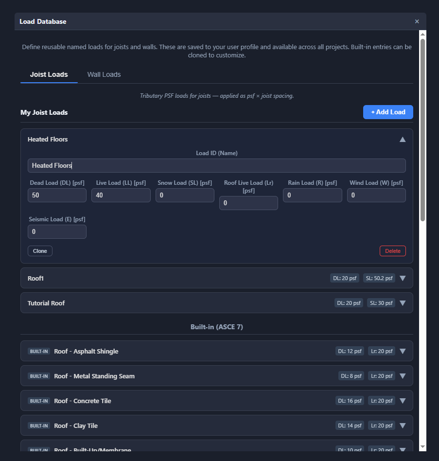
Joist
Regions at 12 / 16 / 19.2 / 24″ o.c. with custom angle and tributary width.
03DIM · GLB · LVL
Header
Spans the opening with trimmer and king studs — size and count for each.
04DIM · GLB · LVL · PSL
Column
Stack types and tributary area; auto-places at beam ends.
052×4 · 2×6 STUDS
Load-Bearing Wall
Stud size and spacing, wall height, and stack type per level.
06W-SHAPES · HSS
Steel Beam
A992 / A500 / A36 grades, Cb lateral bracing, ASD or LRFD.
07W-SHAPES · HSS
Steel Column
K-factor with Euler buckling; rotatable cross-section, auto-place at steel beam ends.
08CONCRETE
Spot Footing
Width × length × thickness, f′c, rebar both ways, bar sizes #3–#11.
09CONCRETE
Continuous Footing
Width and thickness checked against allowable bearing, with the wall on the footing.
10CONCRETE
Pier
Square or round, with ties, k-factor, and rebar count and size.
11CMU · CONCRETE · ICF
Foundation Wall
Type, thickness, and height against backfill height and soil density, with f′m for masonry.
12CAST-IN-PLACE
Retaining Wall
Stem taper, toe and heel, shear key, surcharge, and sloped backfill — strength plus stability.
13STEEL
Anchor Bolt
Diameter 3/8″–1″, spacing, and embedment depth.